Anatomy of a QR Code: What Each Pattern Actually Does
By OwnQR · Published · Updated
A QR code looks like a grid of black and white squares, but not every square stores your message. Some parts help a reader find the symbol, determine its orientation, sample the grid, or recover data. Others carry the encoded information and error-correction codewords. The clear area outside the square matters, too.
The three large corner squares are finder patterns. The smaller repeating features are alignment patterns. Alternating dark and light modules form timing patterns. Around and between them are format and version information, data, and error correction. Understanding these parts is useful when designing graphics around a QR image or troubleshooting a symbol that is difficult to recognize.
A module is one square cell in the QR grid. In a standard QR Code, the grid ranges from 21 × 21 modules (Version 1) to 177 × 177 modules (Version 40), increasing by four modules per side for each version. DENSO WAVE's standardization overview describes that size range. For the general introduction before going deeper, see What Is a QR Code?.
The parts of a QR code, at a glance
| Part | Where to find it | What it does |
|---|---|---|
| Finder patterns | Three large square targets near the corners | Help locate the symbol and establish its orientation |
| Separators | Light modules bordering each finder pattern | Keep those patterns distinguishable from nearby modules |
| Timing patterns | Alternating dark/light lines between finder areas | Help a reader establish the spacing and positions of modules |
| Alignment patterns | Smaller square targets inside larger versions | Help account for image distortion and support grid sampling |
| Format information | Small reserved areas near the finder patterns | Encodes the error-correction level and mask selection |
| Version information | Reserved areas in Versions 7–40 | Encodes the version of larger symbols |
| Fixed dark module | One prescribed dark module immediately to the right of the lower-left finder area, at row size minus eight and column eight | Part of the standard function-module layout |
| Data and error correction | Remaining usable modules | Carry encoded information and redundancy |
| Quiet zone | Clear border outside the symbol | Separates the symbol from its surrounding design or background |
The table describes the standard square Model 2 QR Code. Other families such as Micro QR and rMQR use different layouts. See DENSO's family overview for those distinctions.
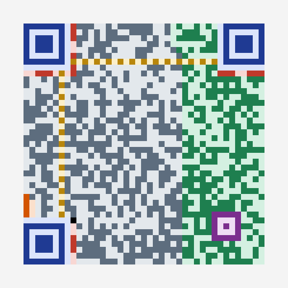
Figure: A Version 6 QR code annotated by module role. The figure is based on a documented offline software audit, not an outdoor or print-scanning experiment.
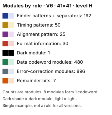
Figure legend: How the color groups map to structural features and codeword areas.
What happens when a QR code is viewed at an angle?
Perspective distortion occurs when a square QR code is photographed obliquely: its sides may appear slanted or its corners may no longer form a square in the camera image. A reader must locate the symbol and estimate where its module grid lies before sampling the dark and light cells. The three finder patterns help establish position and orientation; the smaller alignment patterns in Model 2 QR codes provide additional reference points for distorted images. Model 2 symbols carry alignment patterns only from Version 2 upward; Version 1 has none, so a Version 1 code offers no interior reference points beyond its finder and timing patterns (see Alignment patterns for the per-version count). DENSO WAVE describes alignment patterns as helping correct distortion in its official Model 2 explanation.
This does not mean every angled, folded, curved, or blurred print will scan. Severe viewing angles, glare, occlusion, and low resolution can prevent reliable recognition even when the QR structure is valid. For a physical sign, keep the code flat and unobstructed where practical, preserve the specified quiet zone, and test the actual printed sign from expected viewing positions and devices before relying on it. No camera or print test is claimed here.
1. Finder patterns: why the three big squares matter
The most recognizable QR elements are three concentric square targets: top-left, top-right, and bottom-left. Their arrangement helps a reader recognize a candidate symbol and determine its orientation. They are structural features, not three separate pieces of encoded content.
A line through the center of a finder target follows a dark/light run-length sequence of 1:1:3:1:1. DENSO describes that contrast ratio as an important part of the pattern's detectability. In a software inspection of a QR symbol produced by the encoder used in OwnQR, we observed the expected sequence and a light separator immediately beyond it. The check inspected the module matrix; it did not involve a physical camera.
Design implication: do not treat the three targets as empty decorative squares. Covering them with a logo, crop, or busy graphic can interfere with the information a reader uses to recognize the code.
Pre-print check after adding a logo or crop
We recommend these checks before printing; they do not guarantee successful scanning with every reader.
- Inspect all three finder targets. Compare the final exported artwork with the original code. Check that each target's concentric rings and surrounding light separator remain intact. The 1:1:3:1:1 ratio described above provides a useful visual reference for the wider dark center.
- Check for cropping or overlays. We recommend ensuring that no frame, bleed or crop trims the targets, and that no logo or overlay touches a target or its separator. Avoid tints, gradients or overlays on the targets, which can reduce contrast.
- Preserve the quiet zone. Keep a clear margin around the whole symbol, with no printed artwork intruding. DENSO WAVE's code-area guidance states that QR Code requires a four-module margin on every side.
- Decode the actual print file at final size. Show or print the exact PDF or image intended for production at its intended final size; check it with two different readers, such as a phone camera and a separate scanning app, and confirm the decoded URL or text. An on-screen decode may not match how the printed result scans.
- Test a printed proof. Scan a proof at its intended size, preferably on the intended material and finish. If a check fails, remove or shrink the logo, widen the crop or margin, or return to the original generated code; re-export and repeat the checks.
2. Separators and timing patterns: locating the grid
A separator is the light border immediately around a finder pattern on the symbol side. It prevents neighboring modules from visually merging with the finder target. A timing pattern consists of an alternating line of dark and light modules, helping the reader determine the rhythm and location of the grid cells between the larger corner structures.
These are different jobs. Finder patterns identify the target-like structures; separators help isolate them; timing patterns provide repeated spacing cues. If you redraw a QR code manually, making the data region look plausible is not enough—the reserved structural pattern locations still matter.
What if timing modules are damaged? In a first-party software-only experiment reported for this guide, two decoders (jsQR 1.4.0 and zxing-cpp) decoded 1,772 of 1,772 clean, upright synthetic QR images after one, two, half, or all timing modules were flipped (Versions 1–3, error correction L and M); no incorrect payloads were reported. A separate data-module damage control decoded 268 of 612 images with half the selected data modules flipped and 0 of 600 with all flipped. This is a bounded observation, not a guarantee that a damaged timing pattern will scan: it did not test perspective distortion, blur, low resolution, physical printing, or phone cameras. Timing modules provide geometric sampling cues rather than payload bits; their prescribed locations and role are described in the PHP-QRCode implementation terminology and Thonky's module-placement reference. Preserve them in real artwork and test the finished print with intended readers.
3. Alignment patterns: the smaller square targets
As QR versions grow, additional small square patterns are placed at specified positions. These alignment patterns are not copies of the three corner finders. They give the reader reference points that can help account for distortion when mapping an image back to the underlying QR grid. DENSO's Model 2 explanation describes alignment patterns as a key improvement over Model 1.
Version 1 has no alignment patterns. The source-code module census counted one alignment pattern in each of Versions 2–6, six at Version 7, and 46 at Version 40. These numbers describe complete alignment targets classified by the encoder, not a new requirement about a printed image. Alignment patterns can occupy positions along the timing lines; that matters when counting each kind of module. A naive calculation that treats the entire timing line as exclusively “timing” will overcount the timing category on larger versions.
4. Format information, version information, and the mask
A QR image also contains metadata that is not the user's text or URL. The format information identifies the error-correction level and the mask pattern used for the encoded symbol. The version information is present from Version 7 onward and identifies the larger symbol's version. Those fields are protected with error-detecting or error-correcting information in their prescribed bit structures.
A mask is a selected pattern that changes how dark and light modules are distributed in the encoded matrix. Standard QR encoders can choose among eight mask patterns to improve the symbol's visual characteristics under specified rules. It does not change the underlying destination or message. The encoder chooses a mask using prescribed assessment rules; the mask is not encryption and is not an application-specific QR type.
For a closer explanation of why some codewords can survive damage, use the existing QR code error-correction guide. The correction level and the module-positioning structures solve related but different problems.
The mask and format fields are parts of the symbol's structure; they are not alternatives to the underlying data modes. For a separate explanation of what the encoder does with digits, text and bytes, read QR code encoding modes. The distinction matters when a symbol grows denser: changing the payload or encoding choice can affect version and capacity without changing the purpose of its finder patterns.
Why do two generators make different-looking codes for the same URL?
Two generators can encode the same exact URL into QR symbols that look different without either being incorrect. The QR Code specification defines the symbol structure and how its encoded data is interpreted, but an encoder has choices when constructing a valid symbol. It can select a mask pattern, an error-correction level, a QR version (grid size), and how the input is divided into encoding modes. Those choices can change the dark-and-light module layout even when the decoded URL is identical. DENSO WAVE explains the QR Code's standardized structure and versions; the Segno library's comparison of QR encoders illustrates implementation differences, including mask selection.
To check two different-looking codes, decode each image using a QR decoder and compare the resulting text character for character, including the URL scheme, capitalization, path, query string, and any trailing slash. If the decoded strings match exactly, the two symbols carry the same text even if their patterns differ. If they do not match, investigate the input or generator settings rather than assuming the designs are interchangeable. This is a software-level comparison of encoded content, not proof that both images will scan equally well on every camera or after printing.
5. How much of a QR code is structure instead of data?
The answer changes with the QR version. Smaller symbols devote a greater share of their grid to finder patterns and other mandatory structural features. Larger symbols gain many more positions for encoded data and error correction.
For a software-only module census, OwnQR classified every module in QR Versions 1 through 40 using the Nayuki qrcodegen encoder bundled with qrcode.react 3.2.0. A script followed the encoder's function-module placement order and compared its classification with the encoder's data-module totals; there were zero mismatches across the 40 versions. The scripts and result tables were retained for QA but are not linked for public download here. A separate set of generated symbols was checked with the jsQR 1.4.0 decoder; these are software inspections, not independent third-party or phone-camera tests.
| QR version | Grid size | Share classified as function modules | Approximate remaining share* |
|---|---|---|---|
| Version 1 | 21 × 21 | 52.83% | 47.17% |
| Version 2 | 25 × 25 | 42.56% | 57.44% |
| Version 7 | 45 × 45 | 22.57% | 77.43% |
| Version 10 | 57 × 57 | 14.80% | 85.20% |
| Version 25 | 117 × 117 | 7.17% | 92.83% |
| Version 40 | 177 × 177 | 5.37% | 94.63% |
The remaining modules include data plus error-correction coding and encoding overhead. They are not an equal percentage of unrestricted user-readable text. These are counts from one encoder implementation under a defined classification method; they are not measurements of camera scan success.
This is why the answer to “How many little squares are data?” cannot be one universal percentage. The same three large corner finders remain recognizable, but their fraction of the grid becomes smaller as the version grows.
What did the census count?
The method classified 147 finder-pattern modules and 45 separator modules per standard symbol, plus 30 format-information modules and one prescribed dark module. From Version 7 onward, the classification also includes 36 version-information modules. Timing modules and alignment-pattern modules vary by version. In the census, timing modules counted as 10 at Version 1, 48 at Version 7, and 272 at Version 40; some positions along larger timing lines were occupied and categorized by alignment patterns instead.
In the Version 40 census, 1,681 of the 177 × 177 positions were classified as function modules. That count does not describe the data capacity or the physical size of a printed code.
6. How do we know the format bits were really there?
A separate software test generated 96 QR symbols across three versions (2, 7, and 25), four error-correction levels, and eight mask choices. We read the format-information bits back from each resulting symbol. In all 96 of 96 cases, the decoded format information matched the chosen error-correction level and mask; the format checks passed, and both redundant copies agreed. Version information in the Version 7 and 25 cases also read back correctly. The independent software decoder successfully decoded all 96 examples.
That evidence supports the correctness of the selected test paths. It is not a blanket guarantee that every possible QR image, device, or print condition will work, nor is it a phone-camera field test.
7. The quiet zone: the invisible part of the design
The quiet zone is not a printed ring of QR data. It is the clear space immediately around the entire symbol. For a standard QR Code, DENSO specifies at least four modules of margin on each side. Micro QR has a different two-module margin specification. See DENSO's code-area guidance for the standard QR Code requirement.
Why does this matter? A QR code placed flush against text, a busy photograph, or another dark pattern gives a reader fewer visual cues about where the symbol ends. A clean margin helps separate the intended QR pattern from its surroundings.
In a software-only check of 24 ideal digital images (three versions, four quiet-zone widths, and two pixel scales), jsQR 1.4.0 decoded the test set even when some examples had less than four modules of blank margin. That does not override the four-module requirement and says nothing about phone-camera performance, print quality, or cluttered real-world backgrounds. The practical recommendation remains to preserve the specified quiet zone rather than designing to a decoder's best-case tolerance.
8. What parts should you avoid changing?
If you are designing around a QR code rather than implementing an encoder, the safest approach is to let a standards-conforming generator create the complete symbol and keep its required structural regions intact.
- Do not crop or cover finder patterns. Those are crucial recognition landmarks.
- Do not erase timing or alignment patterns to make room for branding. They support the grid's geometry.
- Preserve the quiet zone around the outer edge.
- Do not infer that error correction makes arbitrary edits safe. It adds redundancy, not a guarantee for every damaged image.
- Keep the encoded destination understandable and test it. A mathematically valid symbol can still encode an incorrect URL.
For a basic URL symbol, use the OwnQR QR code generator, and inspect the final exported image to ensure the symbol has sufficient clear space around it. Do not assume decorative frames or surrounding graphics preserve the necessary margin without checking the actual output.
Frequently asked questions
What are the three big squares on a QR code?
They are finder patterns, used to help a reader locate and orient the symbol. Their prescribed internal dark/light structure is different from the surrounding data region.
What is a QR code alignment pattern?
It is a smaller reference target included in larger QR versions. It helps support reading when the symbol image is geometrically distorted.
What is a timing pattern?
An alternating line of dark and light modules that helps establish the spacing and positions of the grid cells.
Why is there a white border around QR codes?
That clear border is the quiet zone. A standard QR Code needs at least four modules of clear margin around it under DENSO's published guidance.
Does every QR code have the same number of squares?
No. Standard square QR Codes range from Version 1 (21 × 21 modules) to Version 40 (177 × 177 modules). The encoded content and correction setting influence the version selected.
Is every square either a finder pattern or user data?
No. Format information, alignment patterns, timing patterns, the quiet zone, and error-correction data play distinct roles. The quiet zone is outside the grid, not inside it.
Are error-correction patterns the same as alignment patterns?
No. Alignment patterns help locate module positions; error-correction codewords add redundant information that can assist data recovery. Those are different mechanisms.
Does a QR code still work with no quiet zone?
Do not rely on that. Although a software decoder read some ideal images with reduced margins in a limited experiment, that is not evidence for real-world reliability and does not remove the standard four-module margin requirement.
Sources and test limitations
The names and functions of QR structures follow DENSO WAVE's official documentation, its Model 2 explanation, and its margin requirements. Module percentages and format-bit read-back results were produced with Nayuki qrcodegen as bundled in qrcode.react 3.2.0 and decoded in the separate test with jsQR 1.4.0. Scripts and outputs were retained for internal QA; no publicly downloadable replication package is linked here. This AI-assisted article has not received independent human technical review. No smartphone scanning or physical printing was performed.