How to Make a QR Code Stencil: Bridges, Islands and What to Test
By OwnQR · Published · Updated
A QR code looks like a simple arrangement of black and white squares—until you try to cut it from one sheet of material. Some interior pieces fall away, and the remaining stencil no longer represents the image you started with. The solution is to add bridges: narrow strips that connect isolated pieces of stencil material to the surrounding sheet. The challenge is that every bridge changes the pattern a scanner sees.
A good QR stencil is therefore an engineering compromise, not merely a vector export. If you need a refresher on the symbol's structure before changing its shapes, start with the QR code fundamentals guide. Start with a short destination, identify the islands, add the fewest practical bridges, and test the finished mark rather than relying on a digital preview. The F.A.T. Lab QR_STENCILER project is an example of a dedicated stencil-making tool first published in 2011, not a guarantee of compatibility with today's QR generators, file formats, browsers or cutters. The remaining question for today's maker is how to validate a specific material and process.
First decide what will remain and what will be removed
A positive stencil might cut away areas corresponding to dark QR modules, so paint passes through those openings. A negative stencil uses the opposite approach. Neither is automatically safer: reversing dark and light areas changes the recognition conditions and which material regions become disconnected. Keep the intended final image clear before laying out cut lines.
An island is a part of the stencil sheet entirely enclosed by removed material. With a common positive stencil—where dark QR modules are cut open so paint can pass through—retained light modules entirely surrounded by cut-away dark modules become islands. For the anatomy of modules and the surrounding quiet zone, see QR code anatomy. Cut around it, and it drops out. An island might be one square or a cluster, depending on the QR pattern and the material you intend to leave intact. A bridge connects it to a larger intact region. Each bridge is a deliberate interruption in an otherwise faithful image.
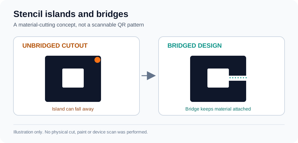
Figure: An illustrative bridge-and-island concept for material cutting. These panels are not QR symbols to scan and have not been physically cut, painted or tested.
Three different things can then go wrong:
| Failure | What you see | First correction to consider |
|---|---|---|
| Mechanical failure | Cut-out pieces fall out or thin bridges tear | Relocate or reinforce bridges; reduce island count |
| Pattern failure | Bridges cover data or damage important structural features | Reposition them; preserve finder, timing and other functional patterns |
| Reproduction failure | Paint bleeds, edges curl or the stencil lifts | Improve contact and material handling; make a new test sample |
The finder patterns themselves also create islands. In a positive stencil, the retained light ring inside each corner finder can become disconnected from the surrounding sheet; in a negative stencil, the dark center can become an island. Some bridge crossing of finder-pattern modules may therefore be mechanically unavoidable. The software dataset's 2,016 bridged examples each included bridges in all three finder patterns. Keep these interruptions as few and as narrow as the material permits, preserve their recognizable overall shape, and avoid disrupting timing and alignment structures where possible. Decoder error correction is not a guarantee that altered finders will remain readable.
Choose a payload that makes the stencil simpler
The content encoded in the QR influences the number of modules. A short, controlled URL is often easier to work with than a long URL containing campaign parameters. For a durable physical installation, a short URL on a domain you control also gives you a simpler maintenance story: the physical code can point to a destination you manage. Its future operation still depends on that destination and domain remaining available.
Export the initial QR as a clean, high-contrast image or vector, then record the exact URL. Avoid decorative overlays while developing the stencil. If the destination changes, regenerate and recheck the pattern before making another cut.
Error correction is a separate trade-off. QR codes have several correction levels, but changing the level changes the encoded symbol and therefore the islands. Higher correction can give the decoder more redundancy, while also requiring more modules overall or a larger QR version in some cases. It does not guarantee a stencil will read. OwnQR's current static URL export uses level H; it is not a stencil designer and does not provide an island-bridging control. The QR code generator can provide a starting pattern, not a cut-ready template.
Why island counts matter (software-only): The same synthetic dataset also counted disconnected retained regions. For a 13-byte sample input, it found 11 islands at error correction L versus 25 at H; for a 59-byte sample input at H, it found 127 islands. These are sample-specific island counts that vary with payload, encoder and stencil polarity, not general counts for all QR codes of those lengths. They explain why a denser pattern can demand substantially more bridge decisions before a cut is feasible.
How wide should the bridges be?
There is no universal bridge width that can be promised for paint, vinyl, acrylic or a laser-cut sheet. A bridge needs sufficient mechanical strength while changing as few QR modules as practical. The correct choice depends on module pitch, cutting kerf, substrate, bleed and illumination. Software experiments can guide which designs to test but cannot certify a physical stencil.
OwnQR software simulation (dataset generated October 25, 2026). A synthetic comparison covered 2,160 generated images and 4,320 decoder attempts, using three payload lengths, four error-correction levels, several module resolutions, and alternative bridge placements. The software rendered each experimental group at 4, 6, 8 and 12 pixels per module under three synthetic conditions: clean, blurred, and blurred with added noise. The table pools those conditions and reports OpenCV QRCodeDetector results for selected bridge-width and placement groups, each with 144 generated examples. All five failures in the 0%-bridge baseline came from the blur-plus-noise group; no bridge-free clean or blur-only example failed in that subset. These are software renderings, not printed-stencil results:
| Bridge width relative to one module | Center placement | Edge placement |
|---|---|---|
| 0% (no bridge) | 139/144 (96.5%) | Not applicable |
| 5% | 142/144 (98.6%) | 139/144 (96.5%) |
| 10% | 141/144 (97.9%) | 137/144 (95.1%) |
| 15% | 139/144 (96.5%) | 137/144 (95.1%) |
| 20% | 136/144 (94.4%) | 136/144 (94.4%) |
| 25% | 129/144 (89.6%) | 139/144 (96.5%) |
| 30% | 111/144 (77.1%) | 134/144 (93.1%) |
| 40% | 62/144 (43.1%) | 108/144 (75.0%) |
How to interpret it: For these synthetic patterns, decode success generally deteriorated when bridges became relatively wide, especially at the center. At widths of 5–20%, this sample does not establish a meaningful improvement over the no-bridge baseline; small numerical differences should not be interpreted as evidence that adding a bridge helps decoding. These rates are not field scan rates, safety thresholds or recommended cutting dimensions. The dataset also contains a condition-dependent anomaly whose cause has not been established; the table deliberately makes no claim about whether blur helps or harms scanning. A second decoder was recorded in the experiment, but the figures here use one specified decoder to keep the comparison consistent.
For a 5 mm QR module, a 10% bridge is 0.5 mm in the design file (a design calculation, not a tested physical tolerance). That calculation does not mean a particular cutter can produce a sound 0.5 mm bridge. Start with the smallest mechanically feasible bridge, keep the source QR unchanged, and evaluate the finished material at full scale.
Change only one design variable per iteration: bridge width, bridge placement, payload, symbol construction or physical reproduction method. Record failures, not only successful scans.
What changes when stenciling a QR code onto a curved bottle?
A bottle's curved surface introduces an additional physical verification problem: a square pattern may appear compressed or distorted from some viewing angles, and glare, seams or surface texture may interfere with the camera's view. Do not infer a reliable bottle diameter, bridge width or scanning distance from the flat, software-only results above. DENSO WAVE explains that QR readability depends on the size of individual modules and the reader's resolution in its module-size guidance, and that a clear four-module quiet zone must surround the symbol.
For a bottle prototype, place the QR where the viewing surface is as locally flat and unobstructed as practical, keep the quiet zone clear, and make a full-scale physical sample using the intended stencil, paint and finish. Test it with the bottle turned through realistic viewing angles, under expected lighting and on intended phones; record failures as well as successful scans. These are proposed checks, not tests performed for this article. A successful flat-screen software decode cannot establish that a curved, reflective bottle will scan reliably.
A practical stencil-making workflow
- Choose a stable destination. Prefer a concise URL and confirm it opens the intended page. Avoid embedding personal details directly in a public pattern.
- Generate the QR. Save the exact source image and, if available, a vector export. Do not assume a graphics program will preserve module geometry during resizing.
- Identify disconnected regions. Choose positive or negative polarity first. In a vector or cutting application, import the clean QR source, trace or convert the module shapes to editable paths without smoothing away square corners, and determine which retained pieces are disconnected from the surrounding sheet. Mark those islands, including the relevant rings or centers of the three finder patterns. Use a specialist stencil tool only if you can validate its output and compatibility.
- Add bridges and unite the cut geometry. At chosen island connections, draw narrow rectangles or paths measured against the actual QR module pitch. Use the software's union/subtract operations so the bridges become part of the retained stencil sheet rather than loose shapes. Some finder crossings are necessary; minimize them and avoid cutting across timing or alignment patterns where possible. Recheck the exported paths for detached islands and save each design revision.
- Export a cut-ready vector and check it. Inspect path closure, accidental duplicate outlines, scale, kerf allowance and the cutter's accepted vector format. Render the merged paths back into a QR-like black-and-white image and attempt software decoding as a screening step, not as proof that a physical sample will work. Confirm your cutter can reproduce the selected feature sizes.
- Make a physical sample. Use the real paint, chalk, film or cut material, not just a desktop print preview.
- Test the result. Scan the completed mark on more than one device, at realistic viewing positions and lighting, and verify the destination rather than merely seeing a scan prompt.
- Document the version. Keep the source URL, stencil file, material, date and photos together, so replacements can reproduce the tested design.
Match the fabrication method to the sample: a knife or vinyl cutter needs bridges that remain attached during weeding; laser-cut sheet needs room for kerf and heat-affected edges; spray paint needs control of overspray and stencil lift; chalk or other temporary markings need a surface and weather test. These are planning differences, not measured pass rates or recommended material tolerances. Follow equipment safety instructions and obtain permission before marking a surface.
What to check after painting or cutting
A digital symbol can decode while a physical one fails. Check four conditions before relying on a public stencil: (1) the stencil actually held the islands; (2) dark and light regions remain distinguishable; (3) there is a clear unmarked area around the symbol; and (4) the code resolves to the intended URL. A scan on your own phone is useful, but a second phone and a second viewing position reduce the chance of overlooking a device-specific problem.
| Symptom | Likely category | Sensible next step |
|---|---|---|
| Stencil tears on removal | Mechanical | Change bridge location or material |
| Paint joins neighboring squares | Reproduction | Reduce overspray; retest the finished mark |
| Scanner does not recognize the image | Structure or reproduction | Compare the final mark to the source QR and inspect finder patterns |
| Scanner recognizes the QR but page fails | Destination or network | Open the actual URL directly and inspect the service |
| Works once but not in ordinary light | Environmental | Repeat with realistic illumination and device angles |
For an outdoor installation, inspect the mark again after exposure and maintenance. Weather durability depends on the substrate and application; a software simulation does not establish an outdoor service life.
Once a stencil is installed in a public place, its upkeep becomes a separate concern from whether the original artwork can be decoded. Staff should inspect the surface for damage or unauthorized overlays and keep a trusted copy of the intended destination. The printed QR tampering guide provides an operator checklist. These maintenance steps do not constitute evidence that this stencil design was physically tested.
Can the stencil be made from any QR code?
Not reliably. A dense code with many tiny modules can create a large number of islands and fragile features. That is a reason to simplify the destination first, not a reason to assume error correction will rescue a complex stencil. A vector SVG improves geometric editability, but it does not add the bridges by itself. The high-resolution QR export tool can help produce a clean source image for downstream design; it does not insert bridges or demonstrate that a cut stencil will scan.
Frequently asked questions
Can I reuse one stencil design with a different URL?
Not safely without checking. Changing the URL can change the underlying module pattern, islands and required bridges even when the printed square has the same dimensions.
Where should I add the first bridge?
Identify a retained-material island and connect it to the sheet with the fewest practical crossings. Bridges across each finder's enclosed region may be necessary; keep those bridges narrow, preserve the recognizable finder shapes, and avoid disturbing timing and alignment patterns where possible. Verify each revision as a QR image before attempting a physical cut.
Why might a digitally readable stencil fail outdoors?
Paint bleed, rough surfaces, glare, weather and damaged margins can affect a real camera. A software pass measures none of those physical effects.
Should I convert the QR to SVG before cutting?
Vector paths help with editing and cutting geometry, but an SVG export does not automatically preserve isolated islands. The bridge design and the final material still need checking.
How much blank space should I leave around a finished stencil?
Keep an uninterrupted light margin around all four sides of the QR pattern, including after paint bleed or trimming. DENSO WAVE specifies a QR quiet zone four modules wide. A visually clear margin in a digital file does not prove that paint, nearby lettering or a textured surface preserves it on the finished mark.
Sources
Preparation and review: This guide was prepared with AI assistance and has not received an independent expert review. The QR stencil figures are software-only simulations, not physical tests. Article revised November 10, 2026.
- F.A.T. Lab, QR_STENCILER and QR_HOBO_CODES — project published 2011; study/event period: 2011 maker-project demonstration; accessed October 25, 2026.
- DENSO WAVE, How to make a QR Code — QR quiet-zone requirement: four modules per side; publication date: NOT_PROVIDED; study/event period: NOT_APPLICABLE (technical reference); accessed November 10, 2026.
- DENSO WAVE, Error correction of QR Code — publication date: NOT_PROVIDED; study/event period: NOT_APPLICABLE (technical reference); source rechecked November 10, 2026.
- OwnQR synthetic software experiment, dataset generated October 25, 2026: 2,160 generated images and 4,320 OpenCV-family decode attempts, with bridge width and position varied; specific rates above use OpenCV QRCodeDetector results. Study/event period: October 2026. No stencil was cut, painted or phone-scanned; this is not a fabrication recommendation.